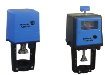
来源:本站

调试说明
A. 安装执行器及阀门(具体操作见安装说明)。
B. 关 闭 执 行 器 电 源 开 关 ( V A P 0 0 0 - - C 电 源 开 关 在 执 行 器 底 板 后 侧 下 方 位 置 ,
VAP 000- -C无电源开关)。
C. 接线完毕(见接线说明)。
D. 将拨码开关设定到需要的位置(拨码开关可带电设置)。
E. 打开执行器电源开关。
F. 自适应(出厂默认为上电自适应):此步骤的目的为使执行器与阀体进行行程匹配:
) 打开执行器电源,执行器自动进入自适应状态。
) 运行指示灯(RUN)闪烁(频率约为 Hz),执行器轴先伸出运行至下极限,然 后在缩进运行至上极限。(此时执行器将不受控制信号的控制)
) 约 分钟后指示灯停止闪烁,此时执行器与阀体的自适应结束,阀体与执行器的 配合调节完成。此时执行器的运行方向由控制信号控制
G. 开度调节:通过调节开度电位器实现阀门最大开度在 00%至 0%范围内连续调节, 灵活的调节阀体内的相对流量与其开度间关系: 00%- 0%开度区间内均分为高 低灵敏度, 0%- 0%开度区间内均为低灵敏度。
注明: . 当执行器在通电情况下,若需自适应,按下执行器电路板上的红色按键 s以上,执行器进入 自适应状态。自适应现象与( )( )现象相同。
. 如需更改自适应模式,可通过调节第七位拨码进行自适应模式选择设定,见拨码开关设定说明。
Wiring Diagram
A. Assemble the actuator with valve body. ( Please refer to installation instructions)
B. Turn off the power switch of actuator.(Power switch is under the right side of VAP 000- -C
actuator, no power switch for VAP 000- -C)
C. Finish the wiring. (Please refer to wiring diagram)
D. Set DIP switches as required. (DIP switches can be set when power on) E. Turn on the power switch of actuator.
F. Self-stroking. (Factory setting: self-stroking starts automatically when power on each time) :
The purpose of this step is to make the actuator matching with the stroke of the valve body.
) Turn on the power switch, self-stroking starts automatically.
) Running light (RUN) flickers (frequency Hz. Actuator axes extends until down limit position, then retracts to up limit position. This moment, actuator can not be controlled by control signal.)
) Running light (RUN) stops flickering after appr. minutes when self-stroking finish. Now actuator matches the stroke of the valve body. Actuator can be controlled by control signal.
G. Aperture regulating. Biggest stroke of the valve can be adjusted from 0%~ 00% of its original stroke by regulating the aperture potentiometer. Flow rate can be regulated neatly.( 0%~ 0%, only low sensitivity of control signal. 00%~ 0% high and low sensitivity selectable.)
Remarks: . When power on, self-stroking can also be operated manually by pressing the red self- stroking button on PCB for over seconds. Self-stroking cycle repeats as step ) & ).
. If you want to change self-stroking mode, adjust the seventh DIP switch. (Please refer to
DIP switch setting)